


- Tags can be read-only or read-write
- Has a unique identification number
- Tag memory can be factory or field programmed, partitionable, and optionally permanently locked
- Bytes left unlocked can be rewritten over more than100,000 times
Types of Tags
Active
- Tag transmits radio signal
- Battery powered memory, radio & circuitry
- High Read Range (300 feet)
Passive
- Tag reflects radio signal from reader
- Reader powered
- Shorter Read Range (4 inches - 15 feet)
Tags can also be classified based on
1. Memory
- Size (16 bits - 512 kBytes +)
- Read-Only, Read/Write or WORM
- Type: EEPROM, OTP, FeRam
2. Arbitration (Anti-collision)
- Ability to read/write one or many tags at a time
3. Frequency
- 125KHz - 5.8 GHz
- Physical Dimensions
- Thumbnail to Brick sizes
Internal block diagram of tags

Operating frequency
The operating frequency is the electromagnetic frequency the tag uses to communicate or to obtain power. The em spectrum in the range in which RFID typically operates is usually broken up into
LF---- <135khz>
HF---- 6.78MHz, 13.56MHz, 27.125MHz, 40.68MHz
UHF--- 433.92MHz, 869MHz, 915MHz
Microwave-- 2.45GHz, 5.8GHz, 24.125GHz
Coupling
A tag’s coupling mechanism determines the way a ckt on the tag and circuit on the reader influence each other to send and receive information or power. The kind of coupling a tag uses directly affects the read range between the tag and reader.
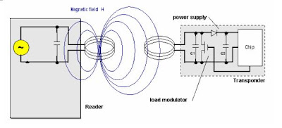
Inductive Coupling
Inductively coupled transponders (tags) are almost always operated passively. This means that all the energy needed for the operation of the microchip has to be provided by the reader. For this purpose, the reader's antenna coil generates a strong, high frequency electro-magnetic field, which penetrates the cross -section of the coil area and the area around the coil.
A small part of the emitted field penetrates the antenna coil of the transponder, which is some distance away from the coil of the reader. By induction, a voltage Ui is generated in the transponder's antenna coil. This voltage is rectified and serves as the power supply for the data carrying device (microchip). A capacitor C1 is connected in parallel with the reader's antenna coil, the capacitance of which is selected such that it combines with the coil inductance of the antenna coil to form a parallel resonant circuit, with a resonant frequency that corresponds with the transmission frequency of the reader. Very high currents are generated in the antenna coil of the reader by resonance step-up in the parallel resonant circuit, which can be used to generate the required field strengths for the operation of the remote transponder.
The antenna coil of the transponder and the capacitor C1 to form a resonant circuit tuned to the transmission frequency of the reader. The voltage U at the transponder coil reaches a maximum due to resonance step-up in the parallel resonant circuit.
As described above, inductively coupled systems are based upon a transformer-type coupling between the primary coil in the reader and the secondary coil in the transponder. This is true when the distance between the coils does not exceed 0.16 l, so that the transponder is located in the near field of the transmitter antenna.
Backscatter Coupling
We know from the field of RADAR technology that electromagnetic waves are reflected by objects with dimensions greater than around half the wavelength of the wave. The efficiency with which an object reflects electromagnetic waves is described by its reflection cross-section. Objects that are in resonance with the wave front that hits them, as is the case for antenna at the appropriate frequency for example, have a particularly large reflection cross-section.
Power P1 is emitted from the reader's antenna, a small proportion of which (free space attenuation) reaches the transponder's antenna. The power P1' is supplied to the antenna connections as HF voltage and after rectification by the diodes D1 and D2 this can be used as turn on voltage for the deactivation or activation of the power saving "power-down" mode. The diodes used here are low barrier Schottky diodes, which have a particularly low threshold voltage. The voltage obtained may also be sufficient to serve as a power supply for short ranges.
A proportion of the incoming power P1' is reflected by the antenna and returned as power P2. The reflection characteristics (= reflection cross-section) of the antenna can be influenced by altering the load connected to the antenna. In order to transmit data from the transponder to the reader, a load resistor RL connected in parallel with the antenna is switched on and off in time with the data stream to be transmitted. The amplitude of the power P2 reflected from the transponder can thus be modulated (à modulated backscatter).
 The power P2 reflected from the transponder is radiated into free space. A small proportion of this (free space attenuation) is picked up by the reader's antenna. The reflected signal therefore travels into the antenna connection of the reader in the "backwards direction" and can be decoupled using a directional coupler and transferred to the receiver input of a reader. The "forward" signal of the transmitter, which is stronger by powers of ten, is to a large degree suppressed by the directional coupler.
No comments:
Post a Comment