Pages

Search Here

Showing posts with label VLSI. Show all posts

Introduction to VLSI

Check out this SlideShare Presentation:

Setup and Hold times

Many designers are familiar with setup and hold time definitions - however, few can identify correctly the launch and capture edges and the slack/violation between two flops during timing analysis. In this post, we will cover setup/hold times in a design with clear examples.

Setup time is defined as the minimum amount of time BEFORE the clock’s active edge by which the data must be stable for it to be latched correctly. Any violation in this minimum required time causes incorrect data to be captured and is known as setup violation.

Hold time is defined as the minimum amount of time AFTER the clock’s active edge during which the data must be stable. Any violation in this required time causes incorrect data to be latched and is known as hold violation.

The setup time in a design determines the maximum frequency at which the chip can run without any timing failures. Factors affecting the setup analysis are the clock period Tclk, Clock to Q propagation delay of the launch flop Tck->q, negative clock skew Tskew, required setup time of the capture flop Tfs and combinational logic delay Tcomb between the two flops being timed. The following condition must be satisfied.

Tfs <= Tclk – Tck->q – Tskew – Tcomb


Hold analysis depends on the Tck->q, combinational logic delay, the clock skew and the hold time requirement Tfh of the capture flop. It is independent of the frequency of the clock. The condition below must be satisfied.

Tck->q + Tskew + Tcomb >= Tfh


Consider the figure below depicting a flop to flop path in the same domain with some combinational logic between them. We will now calculate the setup and hold time slacks in the design based on the given timing parameters.


 Setup and Hold time illustration - Full cycle transfer


For setup checks in single cycle paths, the clock edges that are relevant is shown in the Figure above. The data required time for the capture flop B to meet setup is


Data Required time = (Clock Period + Clock Insertion Delay + Clock Skew - Setup time of the flop) = 8 + 2 + 0.25 -0.1 = 10.15 ns

The data arrival time from the launch flop is


Data Arrival time = (Clock Insertion Delay + CK->Q Delay of the launch flop + Combinational logic Delay) = 2 + 0.1 + 5 = 7.1 ns.


Setup slack is


Setup Margin = Data Required Time - Data Arrival Time = 10.15 - 7.10 = 3.05 ns


Similarly for hold checks assuming the hold time requirement of the flop B is 100 ps, the data expected time is


Data expected time = (Clock Insertion Delay + Clock skew + Hold time requirement of flop) = 2 + 0.25 +0.1 = 2.35 ns.


So the hold time slack is


Hold Margin = Data Arrival time - Data expected time = 7.10 - 2.35 = 4.85 ns


Consider the case where the clock to flop B is inverted (or that the flop is negative edge trigerred). In this particular case, the relevant edges for setup/hold are as shown in the figure below.


Setup and Hold time illustration - Half cycle transfer


In this scenario, the setup margin considering all the other parameters to be the same is


Data Required time = (half_clock_period + clock insertion delay + Ck->Q delay of flop A - Setup time required for flop B) = 4 + 2 + 0.25 -0.1 = 6.15 ns


Since the Data Arrival time remains the same, there is a setup violation of


Setup violation = 6.15 ns - 7.10 ns = -1.05 ns


There is no hold violation since the data arrival time remains the time but the data expected time is any time after (Clock skew + Hold time requirement of flop B)


Data expected time = 0.25 + 0.1 = 0.35 ns


Hold Margin = 7.10 - 0.35 = 6.75 ns


Design of VLSI Systems


Hai friends here i attached the links for the detailed description of following subjects
please go through the links

For direct link to 'Table of contents' please clik here

For publications click here


Clocking Strategies in VLSI Systems


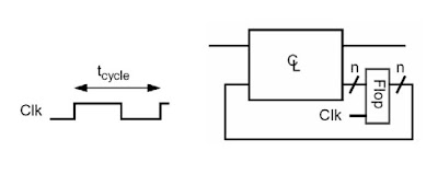
Clock - key to synchronous systems

  • Clocks help the design of FSM where outputs depend on both input and previous states.
  • Clock signals provide reference points in time - define what is previous state, current state and  next state:


Latch vs Flip-Flop


Clock for timing synchronization

Clocks serve to slow down signals that are too fast
  1. Flip-flops / latches act as barriers
  2. With a latch, a signal can’t propagate through until the clock is high
  3. With a Flip-flop, the signal only propagates through on the rising edge
  4. All real flip-flops consist of two latch like elements (master and slave latch)


Latch Timing Parameters


Flip-flop Timing Parameters


Typical Clock System


Clocking Overhead

  • Latches and flops slow down the slow signals
  • Flip-flop delays the slowest signal by the setup + clk-q delay
  • Latches delay the late arriving signals by the delay through the latch


Problem of Clock Skew

  • Not all clocks arrive at the same time
  • Some clocks might be gated (ANDed with a control signal) or buffered There is an RC delay associated with clock wire


Clock Skew and Jitter

Clock skew
  • Spatial variation in temporally equivalent clock edges; deterministic + random, tSK

Clock jitter
  • Temporal variations in consecutive edges of the clock signal; modulation +random noise - Cycle-to-cycle (short-term) tJS Long term tJL
Both skew and jitter affect the effective cycle time

Only skew affects the race margin


Longest Logic Path - Edge Triggered

Unger and Tran, Trans. On Comp. 10/86


Shortest Path Constraint

If launching edge is early and receiving edge is late:


Clocking Strategies

  • Trade off between overhead / robustness / complexity
  • Constraints on the logic vs. Constraints on the clocks
  • Look at a number of different clocking methods:
  1. Pulse mode clocking
  2. Edge triggered clocking
  3. Two phase clocking
  4. Single phase clocking
  • We will only look at system level strategy - consider clocked circuits in the next lecture

Pulse Mode Clocking

Two requirements:
  1. All loops of logic are broken by a single latch
  2. The clock is a narrow pulse
It must be shorter than the shortest path through the logic


Timing Requirements


  • Used in the original Cray computers (ECL machines)

  • Advantage is it has a very small clocking overhead
  1. One latch delay added to cycle

  • Leads to double sided timing constraints
  1. If logic is too slow OR too fast, the system will fail

  • Pulse width is critical
  1. Hard to maintain narrow pulses through inverter chains

  • People are starting to use this type of clocking for MOS circuits
  1. Pulse generation is done in each latch.
  2. Clock distributed is 50% duty cycle
  3. CAD tools check min delay

  • Not a good clocking strategy for a beginning designer


Edge Trigger Flip-flop

  • Popular TTL design style
  • Used in many ASIC designs (Gate Arrays and Std Cells)
  • Using a single clock, but replaces latches with flip-flops


  • Timing Constraints


  • If skew is large enough, still have two sided timing constraints


Two phase clocking


Use different edges for latching the data and changing the output


There are 4 different time periods, all under user control:
  • Φ1 high
  • Φ1 falling to Φ2 rising
  • Φ2 high
  • Φ2 falling to Φ1 rising

Look at shift register again:

  1. If there is a large skew on the Φ2x clock, then the spacing between Φ1 and Φ2
  2. can be increased to make sure that even with the skew, the Φ2 latch closes 
  3. before the Φ1 latch lets the new data pass.
  4. For some setting of the timing of the clock edges, the circuit will work!


Stable signal type

  • We will give signals timing types, so it will be easier to know which latchto use:
  • Output of a Φ1 latch is stable Φ2 (_s2) – good input to Φ2 latch
  • Output of a Φ2 latch is stable Φ1 (_s1) – good input to Φ1 latch
  • Signal is called stable2, since it is stable for the entire Φ2 period


General two phase system

  • Combination logic does not change the value of timing types.
  • No static feedback in the combination logic is allowed either. This makes the system not sensitive to logic glitches.


Why two phase clocking?

It is a constrained clocking style:
  • Synchronous design
  • Two clocks
  • Constrained composition rules

But gives this guarantee:

If you clock it slow enough (with enough non-overlap between edges)
  • It will be a level sensitive design
  • no race, glitch, or hazard problems
  • no skew problems
  • One sided timing constraints
  • Impossible for logic to be too fast

Mealey and Moore Machines


More on latch timing

  • Look a little more closely at latches, to come up with a more complete set of timing types (more than _s1 _s2 signals) that we can use in our synchronous designs.
  1. Look at a latch since this the critical element
  • What is the weakest requirement on the input to a latch?
  • Signal must settle before Φ1 falls, and not change for some time after Φ1 falling, even for a skewed Φ1 (this is usually called the setup and hold times of the latch)


Valid Signal Type

  • The weakest input to a latch is called a valid signal (_v1 _v2)
  1. For a valid signal we need to be sure we can guarantee it meets the setup and hold requirements of the latch
  • To do this we need to have the signal settle off an edge that comes before Φ1 falling. The closest edge is Φ1 rising.
  • The signal should not change until an edge occurs that comes after Φ1 falling. The closest edge is Φ2 rising.
  • If we changed the input on Φ1 falling, most of the time the circuit would work fine. But if it failed, we can’t change the clock timing to make the circuit work -- Φ1 falling controls the changing of the input, and the closing of the latch. Since we can’t guarantee it would be ok a signal that changes on Φ1 falling would not be a _v1 signal. 


Use of valid signal

  • Very useful for precharged logic
  • Is not needed for standard combinational logic with latches
  1. This should always give stable signals
  • Can’t use stable signals if you want to drive two signals/cycle on a wire (multiplex the wire), since the value has to change twice. There are many wrong ways to do it, and only one right way, which is shown below. The values become _v signals. 


Stable Signals

  a. Have even larger timing margins than valid signals

  b. A _s1 signal starts to change sometime after Φ2 rises

  c. A _s1 signal settles sometime after Φ2 rises

  d. Input to the latch must be a _v2 (settles after Φ2 rises)

  e. Output of a latch settles some small delay after input settles
  1. Please note that combinational logic does not change the value of the timing type, even though it does increase the delay of the signal path. The timing types have to do with the clocking guarantee that we are trying to keep. This promise is that the circuit will work at some frequency. A _s1 signal might not settle until after Φ1 rises when the part is run at high-frequency, but the label means that you can make that signal stabilize before Φ1 rises if you need to by slowing the clock down. 


Qualified (Gated) Clocks

  • These are signals that have the same timing as clocks, but they don’t occur every cycle. They are formed by ANDing a ‘_s1’ signal with Φ1 giving _q1, or ANDing a ‘_s2’ signal with Φ2 giving a _q2 signal.
  • The control signal needs to be a stable signal to prevent glitches on the qualified clocks.
  • Qualified clocks can only be used as the clock input to a latch


Summary of Clock Types

The figure shows the timing of all the signals we have discussed with little arrows that indication with clock edge caused the signal to change. Remember the pictures, and the timing types are what the signals look like at slow clock frequencies


Disadvantages of two phase clocking

1. Need four clocks in general
  • Need true and complement of both clocks
2. Still need low skew for good performance
  • The skew increases the cycle time of the machine
  • Need low skew between all the clocks for good performance
  • Want to have Φ1 and Φ2 close to coincident
3. Many systems use clock and its complement instead of 2 phases
  • Needless to say they are very careful about clock skew
  • For these systems it is still useful to maintain 2 phase timing types, since it ensures you connect all logic to the right latches
  • Call Clk - Φ1 and Clk - Φ2, and go from there.
  • Note in this class we will use Φ1 and Φ2 for clocks)

Advantage of Latches Over Flip-Flops

1. If you are going to use Clk and Clk_b and control skew, why not go back
to flip-flops?

2. Many people do:
  • Most designs in industry are based on flip-flops
  • Very easy to verify timing
  • Each path between flip-flops must be less than cycle time
  • Tools check for skew and hold time violations
  • Short paths are padded (buffers are added to slow down the signals)
  • Skew in flip-flop based systems affects the critical path
3. Latch designs are more flexible than a flip-flop design
  • Gives the designer more rope
  • Need to CAD tools to make sure it works
  • Can borrow time to allow a path to be longer than clock period
  • Can tolerate clock skew -- skew does not directly add to cycle time

Single-phase Clocking

Unger and Tan, Trans. On Comp Oct 86


Latch-based Design with Single-phase clock



CHEMICAL VAPOUR DEPOSITION

  • Deposition of a solid material onto a heated substrate via decomposition or channel reaction of compounds contained in the gas passing over the substrate
  • Many materials such as silicon nitride silicon dioxide ,polycrystalline silicon silicon ,and single crystal silicon ,can be deposited via CVD
  • Aspecial case of CVD is called epitaxy or epitaxial layer deposition or vapour phase epitaxy(VPE) , in which case the deposited layer is in single crystal form
  • In CVD process the materials to be deposited enter a reaction chamber in the gaseous or vapour phase and react on or near the surface of the substrates ,which are at some elevated temperatures
  • The chemical reaction that occurs produces the atoms or molecules that are deposited on the substrate surface
A number of different materials can be deposited by the CVD process
  1. Silicon epitaxial layer on a single-crystal silicon substrate
  2. Silicon epitaxial layer deposition on a sapphire
  3. Silicon dioxide deposition
  4. Silicon nitride deposition

EPITAXIAL DEPOSITION


  • The word “epitaxy” is a Greek word ‘epi’ means ‘upon’ and ‘taxy’ means ‘arranged’
  • ie, it is an arrangement of atoms upon a crystal substrate ,so that the resulting added layer structure is an exact extension of the crystal structure
  • There are a number of different chemical reactions that can be used for the deposition of epitaxial layers
Four silicon sources have been used for growing epitaxial silicon–
Silicontetra chloride(SiCl4), dichlorosilane(SiH2Cl2),trichlorosilane(SiHCl3) and silane(SiH4)

Some important Reactions for Epitaxial layer Deposition


  • Silicon tetrachloride has been the most studied and has seen the widest industrial use.The overall reaction can be classed as a hydrogen reduction of a gas
SiCl4(gas) + 2H2(gas) --> Si(solid)+4HCl(gas)
  • The epitaxial layer deposition takes place in a chamber called an epitaxial reactor
  • Horizontal reactor ,Vertical reactor, Cylindrical reactor
  • Horizontal reactors offer lowest cost construction,however controlling the deposition process over the entire susceptor length is a problem
  • Vertical reactors are capable of very uniform deposition, but suffer from mechanical complexity
  • Cylindrical reactors are also capable of uniform deposition due to employment of radiant heating,but are not suited for extended operation at temperature above 1200c

  • The process is carried out in a reaction chamber consisting of a long cylindrical quartz tube encircled by an RF induction coil
  • The silicon wafers are placed on a rectangular graphite rod called a boat
  • This boat is then placed in the reaction chamber where the graphite is heated inductively to a temperature 1200c
  • The various gases required for the growth of desired epitaxial layers are introduced into the system through a control console
  • The basic chemical reaction used for the epitaxial growth of pure silicon is the hydrogen reduction of silicon tetrachloride
SiCl4+2H2 <--> Si+4HCl
  • For producing doped p or n type epitaxial layers, a number of gases can be metered into the reactor tube, including some very small amounts of doping gases,such as B2H6(diborane) for boron doping and PH3(Phosphine) for phosphorous doping of the epitaxial layer

Advantages

  • SiCl4 is non-toxic,inexpensive and easy to purify
  • The reaction making silicon from SiCl4 takes place only at surface and not on the boat or reaction chamber walls

Disadvantages

  • The growth process is accompanied by the diffusion phenomenon which causes an exchange of impurities between silicon wafer and growing film.This prevents the fabrication of an ideal step junction
  • SiCl4 process requires higher temperature and also has slower growth rate

Ion Implantation


  • Technique used to introduce impurities into a silicon wafer
  • Silicon wafers are placed in a vaccum chamber and are scanned by a beam of high energy dopant ions(borons for p-type and phosphorous for n-type)
  • These ions are accelerated by energies between 20kv to 250 kv
  • As the ions strike the silicon wafers ,they penetrate some small distance into the wafer
  • The depth of penetration of any particular type of ion increases with increasing accelerating voltage


Properties of ion implantation


  • The depth of penetration of any particular type of ion will increase with increasing accelerating voltage
  • The penetration depth will generally be in the range of .1 to 1µm

Range distributions


Impurity Distribution of implanted ions:- The distribution of the implanted ions as a function of distance x from the silicon surface will be a Gaussian distribution ,given by

N(x)=Npexp[-(x-Rp)² /2ΔRp²]
x=distance into substrate from surface
Rp=projected range
ΔRp=standard deviation of the projected range
Np=peak concentration of implanted ions


An ion implantation impurity profile


The peak implanted ion concentration is related to the implantation dosage Q by
Np= Q/(2π)½ΔRp =.4[Q/ΔRp]
  • The implantation dosage Q is the number of implanted ions per unit of surface area as given by such units as ions/cm2.
  • The ion density drops off rapidly from the peak value with distance as measured from Rp in either direction

Annealing after implantation


  • After the ions have been implanted they are lodged principally in interstitial positions in the silicon crystal structure and the surface region into which the implantation has taken place will be heavily damaged by the impact of the high energy ions
  • The disarray of silicon atoms in the surface region is often to the extent that this region is no longer crystalline in structure but ,rather amorphous
  • To restore this surface region back to well-ordered crystalline state and to allow the implanted ions to go into substitutional sites in the crystal structure , the wafer must be subjected to an annealing process
  • The annealing process usually involves the heating of the wafers to some elevated temperature often in the range of 1000c for a suitable length of time such as 30 minutes
  • Laser beam and electron beam annealing are also employed. In such annealing techniques only the surface region of the wafer is heated and recrystallized

Advantages

  • Provides much more precise control over the density of dopants(Q) deposited into the wafer,and hence the sheet resistanse.
  • In diffusion process, temperature has to be controlled over a large area inside the oven,whereas in ion implantation technique, accelerating potential and the beam current are electrically controlled from outside
  • Possible to have very low values of dosage(Q) ,so that very large values of sheet resistance can be obtained
  • Performed at low temperatures